
The Black Box Photometer
|
|
|
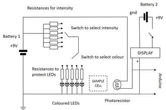
The black box photometer is a simple circuit consisting of a photoresistor and a light source which can be switched between different colours and modified in intensity. The sample is placed in a plastic cuvette between the light source and the photoresistor and the voltage output measured.
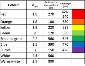
The colours are reasonably precise because they are based on LEDs. Clearly, this doesn't have the wavelength precision of a true slit source but it is a lot better than using photogel filters (which also work).
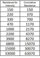
Most people are a bit afraid of electronics and I certainly am not an expert by any means, however, with a little bit of patience it is possible to reduce the apparent complexity of this model even further by using a breadboard to build the circuit and choosing single resistances to adjust the intensity of the light.
The digital readout proposed in this model can also be substituted by a simple voltmeter to measure the voltage directly across the output and ground, although the digital readout has the advantage of being quite precise and easy to use.
Originally, I used a circuit proposed in the article describing a home made spectrophotometer (Tavener and Thomas-Oates, 2007). This worked well but needed an op-amp to work. A conversation with someone who actually plays with circuits and knows what they are doing resulted in the extremely stripped down version presented here in which there are no op-amps or anything other than the light source and the photoresistor. He convinced me with the results that this version is definately usable.
For more detailed instructions for building the black box photometer and some uses see here (in preparation)
2007, Tavener, S.J., Thomas-Oates, J, E., Education in Chemistry (RSC), 151-154 (pdf can be found here)
The colours are reasonably precise because they are based on LEDs. Clearly, this doesn't have the wavelength precision of a true slit source but it is a lot better than using photogel filters (which also work).
Most people are a bit afraid of electronics and I certainly am not an expert by any means, however, with a little bit of patience it is possible to reduce the apparent complexity of this model even further by using a breadboard to build the circuit and choosing single resistances to adjust the intensity of the light.
The digital readout proposed in this model can also be substituted by a simple voltmeter to measure the voltage directly across the output and ground, although the digital readout has the advantage of being quite precise and easy to use.
Originally, I used a circuit proposed in the article describing a home made spectrophotometer (Tavener and Thomas-Oates, 2007). This worked well but needed an op-amp to work. A conversation with someone who actually plays with circuits and knows what they are doing resulted in the extremely stripped down version presented here in which there are no op-amps or anything other than the light source and the photoresistor. He convinced me with the results that this version is definately usable.
For more detailed instructions for building the black box photometer and some uses see here (in preparation)
2007, Tavener, S.J., Thomas-Oates, J, E., Education in Chemistry (RSC), 151-154 (pdf can be found here)